User Tools
Sidebar
Navigation
hardware:lan-bridge:lan-bridge-configuration:slots-tab
Table of Contents
Slots Tab
This is where you configure Ethernet communication slots on the LAN Bridge. One example of is the ability to configure the LAN Bridge to act as a TCP multiplexer and allow more multiple connections to devices or systems that usually only allow a single connection.
This section is broken up into three parts to cover each of the slot configuration areas.
For this tab the Save and Refresh buttons have the same functionality.
The Refresh button will request the settings from the device and display them in System Commander. You will lose any unsaved settings when you click this button.
The Save Button will save any settings you have entered in System Commander to the device.
Slots
This page is under construction. If you require assistance please contact us via our support page.
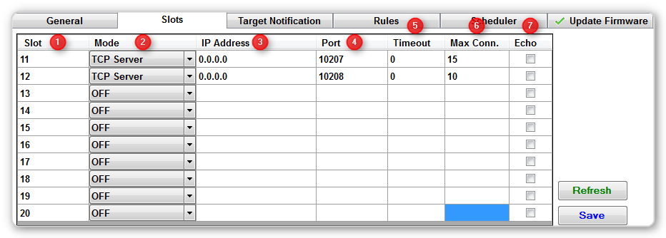
1 - Slot
The LAN Bridge has 10 user definable slots, starting from slot 11. More info on the other slot numbers (below 11) can be found on the LAN Bridge CFLink protocol page.
2 - Mode
Each slot can be defined in one of 5 modes:
- OFF - The slot is disabled.
- TCP Server - Configured the slot to act as a TCP Server and accept incoming connections.
- TCP Client - Configure the slot to connect to a remote TCP Server.
- UDP Unicast - Configure the slot to send/receive data via UDP to a specific IP Address.
- UDP Broadcast - Configure the slot to send/receive data via a broadcast address.
3 - IP Address
Here you define what IP address the slot will use. Depending on the mode, the IP Address is used in varying ways.
- TCP Server - Accept incoming connections only from a specific IP address. Enter an IP Address of 0.0.0.0 to accept incoming connections from any client.
- TCP Client - The IP address defines the remote TCP Server to connect to.
- UDP Unicast - The IP Address defines where the data will be sent to. Data can be received from any IP address.
- UDP Broadcast - The IP Address defines the broadcast address to use. Most commonly, to broadcast to the whole network, use 255.255.255.255. But you can use 192.168.0.255 for example, to only broadcast to machines in the 192.168.0.x subnet.
4 - Port
This defines what port number the communications will take place over for the slot. Valid range is 1-65535.
5 - Timeout
Timeout is only relevant for TCP Server and Client slot modes. This defines how long a TCP Socket will remain open for when no data is received. After the defined time, the socket will close.
If the slot is a TCP Server, the timeout is per incoming connection.
If the slot is a TCP Client, the connection to the server will be dropped and attempted to reconnect in 3 seconds.
6 - Max Conn.
This is only relevant for TCP Server mode. This setting defines the maximum number of clients that can connect at any one time.
The LAN Bridge can accept a total of 25 incoming/outgoing TCP sockets at a time, split between all defined slots exactly as defined in the Max Connection setting.
So the sum of the Max Conn. settings must never be greater than 25 across all slots.
A TCP Client slot counts as 1 connection, so make sure to take that into account in your socket sharing calculations.
7 - Echo
This is only relevant for TCP Server mode. When echo is enabled, incoming commands from one TCP Client are echoed out to all other connected TCP Clients.
Slot Bridging (Subscriptions)
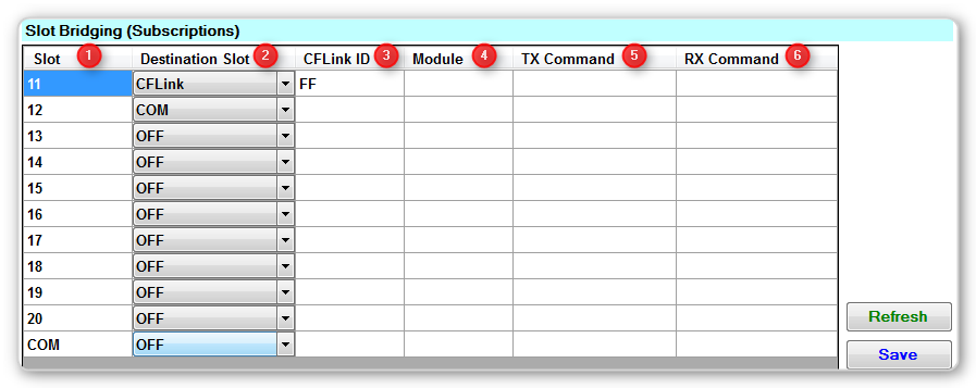
1 - Slot
The slot number to bridge incoming data from.
2 - Destination Slot
The slot number to bridge incoming data to. Data received from the first slot, will be bridged and sent to the destination slot.
3 - CFLink ID
If Destination Slot is configured to CFLink, the CFLink ID is the device on the CFLink network to forward data to/from. This allows you to subscribe a communication slot to a single device on the CFLink bus.
Use a value of FF to broadcast all data received from the Slot to all devices on the CFLink bus. Doing this requires that the incoming data be a valid CFLink Protocol packet or it will be ignored.
4 - Module
If the CFLink ID is used, and the target CFLink device is a modular base unit (ie. MOD4 or DIN-MOD4), this setting is used to bridge the data to only a specific module on the device.
5 - TX Command
If the CFLink ID is used, this setting allows you to define a specific CFLink Command name to wrap all incoming data with.
eg. If you configure the TX Command to be TRLYSET (the command to set a relay state on a CFLink device) then any data coming from the Slot will be first wrapped in the entire CFLink packet before being sent out to the CFLink bus.
So if the incoming data was simply P01:1, then the data would first be wrapped in the TRLYSET command, resulting in the full data being sent onto CFLink as: [F2]<CFLinkID>[F3]TRLYSET[F4]P01:1[F5][F5].
6 - RX Command
If the CFLink ID is used, this setting allows you to define a specific CFLink Command name to look for and strip from all outgoing data before sending back to the Slot.
eg. If you configure the RX Command to be RRLYSTA (the reply notification sent from a relay on the CFLink bus when it changes state) then any relay state data coming from the Destination Slot will be first stripped of all CFLink packet formatting before being sent out to the Slot.
So if the incoming data was [F2]<CFLinkID>[F3]RRLYSTA[F4]P01:1|P02:0|P03:0|P04:1[F5][F5], then the resulting data sent to the Slot would be simply P01:1|P02:0|P03:0|P04:1.
Slot Startup Commands - COMING SOON IN FIRMWARE UPDATE
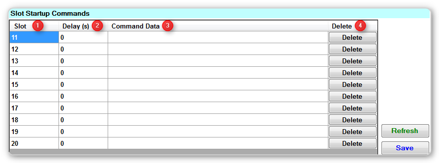
1 - Slot
2 - Delay (s)
3 - Command Data
4 - Delete
hardware/lan-bridge/lan-bridge-configuration/slots-tab.txt · Last modified: 2014/02/17 14:29 by jarrod