User Tools
Sidebar
Navigation
hardware:cf-mini
Table of Contents
CF Mini
The CF Mini is a multi-functional controller with the following features:
- 8 x IR
- 4 x I/O
- 4 x 30V DC Relays
- 1 x RS232/Program
- 1 x CFLink
- 1 x MicroSD Slot
Quick Reference Guide
The CF Mini Quick Reference Guide provides the basic information required to get started on a printable, black and white document that can be easily taken with you to a job site. Find the CF Mini Quick Reference Guide here.
CFLink Protocol
For details on the CFLink protocol supported by the CF Mini, see the CF Mini CFLink Protocol page.
Information Panel
The information panel can be found on the top of the CF Mini.
LEDs
- Power (Blue)
- Off = Power off
- Flashing = Booting or firmware missing
- Solid = Power on and ready
- CFLink Fault (Red)
- Solid = Fault discovered on CFLink bus. Remain solid until reset.
- Reset unit to clear CFLink fault flag and turn off LED.
- CFLink Activity (Amber)
- Flashing = CFLink activity is detected on the CFLink network.
- COM Port Program Mode (Amber)
- Solid = On-board RS232 port is in Program Mode (for communicating with CFLink devices via RS232).
- COM Port RS232 Mode
- Solid = On-board RS232 port is in RS232 Mode (for controlling third part RS232 devices).
- Status (Amber)
- The status LED can be configured to represent the status of any of the CF Mini ports.
- For example, it could represent a relay being closed, reading voltage changes, sending IR, etc.
Recessed Buttons
- Setup
- Press to toggle on-board RS232 Mode
- Reset
- Press to reset the unit. See the Device Resetting page for more information.
Ports
One side of the CF Mini contains 4 sets of connectors as follows.
Input/Output
The top left connector contains 4 IO ports. Each port can be configured as either:
- Dry Contact Input
- Resistance Reading Input (0 to 10,000 Ohms in 100 Ohm increments)
- Voltage Reading Input (00.0 to 10.0 Volts DC in 0.1 Volt increments)
- Voltage Sensing Input (with adjustable thresholds)
- Video Sensing Input (with adjustable thresholds)
- External Relay Output, 0-24V DC (external power supply required)
- LED Output (5V DC, 1mA)
Pinout
- Top Row
- Port 1 Input
- Port 1 Ground
- Port 2 Input
- Port 2 Ground
- Bottom Row
- Port 3 Input
- Port 3 Ground
- Port 4 Input
- Port 4 Ground

Relay
The top right connector contains 4 Relay Ports, 30VDC, 1A each.
Pinout
- Top Row
- Port 1 Common
- Port 1 Load
- Port 2 Common
- Port 2 Load
- Bottom Row
- Port 3 Common
- Port 3 Load
- Port 4 Common
- Port 4 Load
Infrared
The bottom two connectors contain 4 IR ports each, for a total of 8 IR ports.
Pinout
- Top Row
- Port 1 +
- Port 1 -
- Port 2 +
- Port 2 -
- Port 3 +
- Port 3 -
- Port 4 +
- Port 4 -
- Bottom Row
- Port 5 +
- Port 5 -
- Port 6 +
- Port 6 -
- Port 7 +
- Port 7 -
- Port 8 +
- Port 8 -
RS232
The RJ12 port is used to communicate to and from RS232 devices.
Depending what mode the RS232 port is in (indicated via the information panel LEDs), this port can be used for 2 things:
- Controlling and configuring the CF Mini and any other CFLink devices on the CFLink network.
- Communicating with third party RS232 devices such as projectors, TVs, etc.
Socket & Cable Pinouts
All colors used in the diagrams relate to the wire colors in the RJ12 cable that ships with the CF Mini.
If you are using a custom RJ12 cable, then these colors may not match. So check the socket & cable pinouts to relate to your wiring colors.
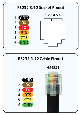
- GND
- RX
- TX
- RTS
- CTS
- GND
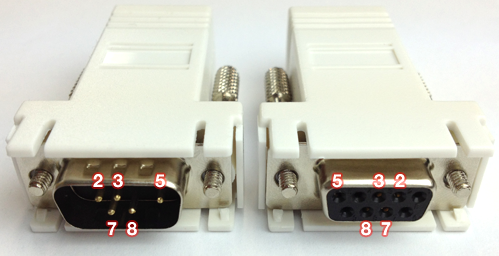
RJ12 Adapter Pinouts
Shipped with the CF Mini are two RJ12 to DB9 adapters (one male and one female) and a single RJ12 cable.
These adapters will convert the on-board RJ12 socket to a standard serial port DB9 connector ready for use in most projects.
If you need a special wiring configuration, simply use any off-the-shelf RJ12 to DB9 adapter and configure the wiring as needed.
All colors used in the diagrams relate to the wire colors in the RJ12 cable that ships with the CF Mini.
If you are using a custom RJ12 cable, then these colors may not match. So check the socket & cable pinouts to relate to your wiring colors.

CFLink
The 5-pin CFLink connector is used to communicate with other CFLink devices on the network.
Pinout
- Isolated Ground
- Data +
- Data -
- Power (9-30V DC)
- Ground
MicroSD
The MicroSD slot is used to expand the on-board memory via MicroSD cards.
Accessories
The CF Mini comes packaged with the following accessories:
- RJ12 to DB9 male adapter
- RJ12 to DB9 female adapter
- RJ12 cable, 1 meter.
Factory Reset
For information on how to rest your device to factory settings, see the Device Resetting Page.
hardware/cf-mini.txt · Last modified: 2013/10/25 05:27 by jarrod