
Modular controller with 4 slots.
Configure any way you need.
Rack-mountable, configure to suit your system requirements using our various hardware modules.
4 module slots
and CFLink BUS.
The modular nature of this controller means you can configure the connectivity based on your system requirements, paying for only what you need.
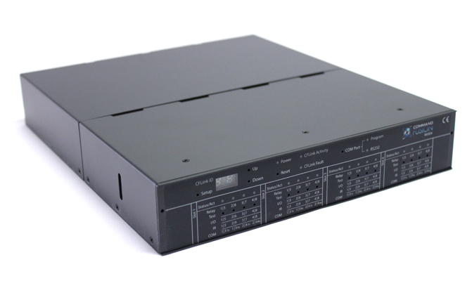
Informative front panel
for status monitoring.
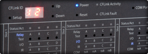
The front panel display offers a range of information, helping diagnose system configuration and activity issues quickly and easily. LED's even light up to tell you exactly what modules are plugged in.
Test buttons
to check connectivity.
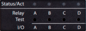
Using the front panel test buttons, you can ensure your connections are all working without the hassle of controlling the unit remotely. Activate relays, send IR codes, trigger dry contact inputs, and so on.
Overview
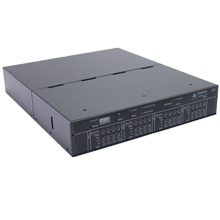
The MOD4 is a rack-mountable, modular controller. Featuring 4 module slots, it can be freely configured to meet your connectivity requirements from job to job. Need 17 RS232 ports? How about 32 IR outputs? No problem. The MOD4 has you covered.
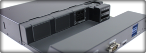
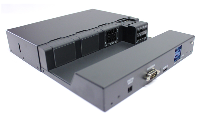
The rear casing of the MOD4 is removable so that modules can be installed/removed as required. It also helps with cable management if required.
Rules Engine
All CFLink devices, including the CF Mini, support a powerful rule triggering engine. This allows you to trigger macros to run when a specific event occurs - such as reading a specific value via the I/O ports, or on incoming data via the RS232 port. Using the rules engine, you can setup basic or complex automation actions.
Rack-mount Kit
Two units of the MOD4 can be installed in a single rack space height (1RU) using the optional RACKIT (rack-mount kit, sold separately).
Modular
Each module slot can be filled with any of our available hardware modules. Combinations of RS232/422/485, IR ports, I/O ports, Relays are up to you. Mix and match the modules to suit your requirements. The MOD4 ships with 4 blank modules, other modules sold separately.
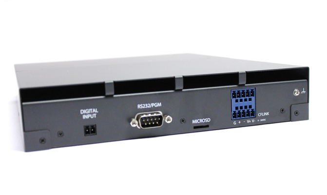
On-board RS232/Program Port
The MOD4 contains an on-board RS232/Program port, which can be used to either control third party RS232 devices, or control the MOD4 and any other CFLink devices on the same CFLink bus from a third party control system.
Hidden Front Panel
The MOD4 comes with a detachable front cover, hiding all the geeky-ness and transforming the MOD4 into a sleek component at home in any home entertainment cabinet. A simple magnet attachment makes it easy to temporarily remove when viewing of the front panel detail is required.
GalleryHigh res photos in downloads section
 MOD4 without front cover
 MOD4 with front cover
 MOD4 rear cover removed showing installed modules
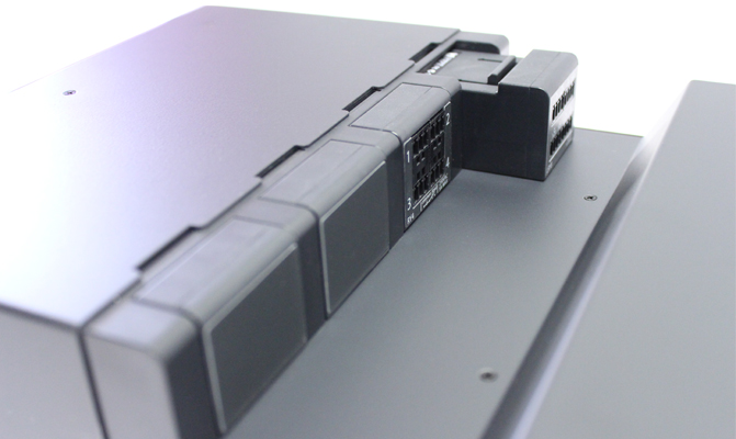
 MOD4 rear cover removed, closeup showing installed modules
 MOD4 rear showing on-board connectivity

Technical SpecificationsSee hardware documentation for more details
| Connectivity | |
|---|---|
| CFLink | 2 looped, detachable 5-pin 3.81mm terminal block for CFLink BUS |
| RS232/PGM | 9-pin DB9 male port for RS232 control of devices; or programming mode which allows both programming and external control of the CFLink BUS devices via RS232 |
| Input | Detachable, 2-pin 3.50mm terminal block for dry contact input |
| MicroSD slot | Spring-loaded memory expansion slot |
| Slot 1-4 | Slots for modules to be installed in (sold separately, shipped with 4 blank modules) |
| Power | |
| CFLink Power | 9-30V DC, 24V DC regulated recommended (power supply is not included) |
| Power Consumption | 250mW maximum |
| Front Panel | |
| Power Indicator | Blue LED indicates power status |
| CFLink Fault Indicator | Red LED indicates error on CFLink BUS |
| CFLink Activity Indicator | Yellow LED indicates CFLink BUS tra ffic |
| Setup Button | Used to start changing the CFLink ID of the unit and also factory reset |
| Up/Down buttons | Up/Down buttons used to change the CFLink ID when in setup mode |
| Reset Button | Reset button restarts the processor |
| COM Port Button | COM port button used to select program or RS232 mode for on-board RS232 port |
| Program Indicator | Yellow LED indicates on-board RS232 port is used for programming or control of CFLink BUS |
| RS232 Indicator | Yellow LED indicates on-board RS232 port is used for control of external RS232 devices |
| Slot 1-4 Front Panel Indicators | |
| Status/Act Indicators | Yellow LED indicates data sent/received to specific module ports. |
| Relay Indicator | Blue LED to indicate a relay module is installed in the specific slot. |
| I/O Indicator | Blue LED to indicate a I/O module is installed in the specific slot. |
| COM Indicator | Blue LED to indicate a COM port module is installed in the specific slot. |
| Test Buttons | The test buttons are used to activate test functionality, depending on the module installed. Activate relays, send configurable IR signals, simulate dry contact input closure, etc. The test buttons can be held to change the Status/Act LEDs to reflect module activity on ports 1-4 or 5-8. Module type indicators will flash to symbolise the activity LEDs are referencing the second group of ports. |
| Physical | |
| Enclosure | Steel & Polycarbonate with dark grey matte finish. Occupies 1RU rack height and 1/2 rack width. |
| Height | 43mm (1.69in) |
| Width | 217.6mm (8.57in) |
| Depth | 259.3mm (10.20in) |
| Weight | 1.8kg (3.97lbs), Shipping 2.0kg (4.41lbs) |
| Environmental & Regulatory | |
| Temperature | 5°C to 45°C (41°F to 113°F) |
| Humidity | 20% to 85% RH, non-condensing |
| Certification | FCC, CE, C-Tick |
| Warranty | |
| Warranty | 5 years limited warranty |
Downloads & Documentation
Manuals
MOD4 Quick Reference Guide includes details like pinout diagrams and general connectivity details.

Single page specification sheet.
Application Diagrams

High Resolution Photos
Coming Soon...
![]()
![]()
![]()
![]()
![]()
© 2026 CommandFusion Pty Ltd. All rights reserved.